
Noise Figure Measurements of Cryogenic LNAs Using the Cold Attenuator Technique
Abstract: This document explains noise figure measurements of cryogenic LNAs using the cold attenuator technique, including the cryogenic test setup, de-embedding, hot and cold noise temperatures, Y Factor, and conversion of noise temperature to noise figure.
Please click here to download the document as a PDF file.
Fields such as radio astronomy, satellite technology and quantum computing involve the detection and processing of very low power signals which would be lost in the noise at ambient temperatures. So the LNAs used in these receivers are cryogenically cooled to operate at temperatures typically down to 15 K, or even less. They are extremely low in noise, and can have noise figure values as low as 0.03dB.
The cold attenuator technique provides a very accurate method of measuring noise figure by placing a passive attenuator in front of the LNA inside a cryogenic dewar, and a standard calibrated noise source outside the dewar at room temperature. The cold attenuator, typically with a value of 20dB, eliminates most of the room temperature noise and reduces the noise signal to a level seen by the amplifier when in use.
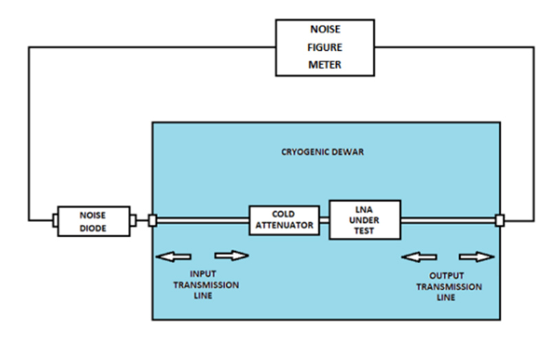
Using a noise diode instead of mechanically switched loads means that rapid measurement speed is possible. However, because the noise diode cannot be directly connected to the input of the LNA using this method, added problems are encountered in comparison to a noise figure measurement at room temperature. The vacuum must be maintained at a high level in order to provide thermal isolation from the walls of the dewar, and the RF and power connections to the LNA must also be thermally isolated.
The cold attenuator improves noise source uncertainty and drastically reduces the off-to-on impedance change of the noise source diode. This provides an excellent 50Ω impedance match to the LNA and greatly increases noise figure measurement accuracy.
In this example the temperature of the attenuator and LNA are 15 K, and the temperature of the input cable is assumed to lie between the ambient temperature (290 K) and the cryogenic temperature (15 K), therefore 152.5 K. The noise diode provides a cold load when in its off state, and the noise power (expressed in terms of temperature) applied to the LNA (Tc) is equal to the physical temperature of the attenuator plus a small contribution from the ambient temperature noise diode (TDcold = 290 K) after having been attenuated by the input cable and the cold attenuator.
In its on state the noise diode becomes a hot load, and the following formula can be used to calculate the noise temperature at its output (TDhot):
TDhot = 290 (10ENR/10 + 1)
So a noise diode with an ENR of 15dB would give a hot temperature of 9461K at its output.
The noise diode, input cable and cold attenuator all contribute to the hot and cold noise power levels at the input connector of the LNA, and the procedure used to determine these values is called de-embedding. The parameters needed to carry out this process are the ENR of the noise diode (provided by the manufacturer), the insertion loss of the input and output transmission cables at the test operating temperature, and the attenuation of the cold attenuator at the test operating temperature. Strictly speaking VSWR should also be taken into account, but this will be negligible if good quality components are used. Other factors affecting measurement accuracy are the calibration of the noise diode and the accuracy of the value of Y Factor calculated by the noise figure meter. All this information is required across the relevant frequency range.
The input and output transmission cables within the dewar should be as symmetrical as possible in terms of insertion loss and phase from the ambient temperature ends to the cryogenic LNA. This requires careful measurement and matching of the components which make up these cables. The input and output cables are firstly connected together inside the dewar and measured for insertion loss over the frequency bands of interest using a vector network analyser. The insertion loss for the input cable is then assumed to be half the value of this measurement.
Once the measured losses of the input transmission cable and attenuator have been found (Lcab [dB] and Latten [dB]), their Loss Factors can be calculated:
Lcab = 10Lcab[dB]/10
Latten = 10Latten[dB]/10
These loss factors can then be inserted into the following formulae, along with the noise diode hot and cold output temperatures and the attenuator and input cable temperatures to find the effective hot and cold noise temperatures at the LNA input, Th and Tc.
Th = ((TDhot + Tcab) / Lcab) · (1 / Latten) + (1 − 1 / Latten)Tatten
Tc = ((TDcold + Tcab) / Lcab) · (1 / Latten) + (1 − 1 / Latten)Tatten
TDhot = 9461 K
TDcold = 290 K
Tcab = 152.5 K
Tatten = 15 K
Lcab = 1.259 (1dB)
Latten = 100 (20dB)
which give values of Th = 91.2K and Tc = 18.4 K
Measurements of Y Factor, or the ratio of LNA output power with noise diode on and noise diode off, are taken using the noise figure meter at selected frequencies across the band.
The noise temperature of the LNA, TLNA, can then be found using the following equation:
TLNA = (Th − YTc) / (Y − 1)
And noise temperature can be converted to noise figure as follows:
NFLNA = 10 log10(1 + TLNA/290)
So for this example, a cryogenic LNA with a Y Factor of 4.57 will have a noise figure of 0.03dB.